Lower hanging fruit: RTC on Adalogger

Code: [ firmware ] [ host PC ]

Well, SD cards are somewhat involved. So I’ve just been working on the easier problem of setting up the RTC: easier because there’s a library for it and all I need to do is setup a connection with Processing so I can configure the real time clock module on SAMD21!

Just so you know, I just learned about [ UNIX time ] and was quite excited to use it because of this [ post ]:

In the end, the only thing that really works for all situations,
is using a single epoch and then converting to timezone offsets
as needed. The unix guys really did get it right way back then.

Also, I should mention that it seems easier to store numbers in the logger’s memory, than to deal with strings like “12:00 AM 05/24/16”. And we could do a re-sync whenever the recorder is programmed so there’s aren’t any significant offsets. Besides, knowing an absolute number, we can always figure out what local times may have been!

But then I decided to not use epoch since the registers themselves are mapped to date/time:

alarm0.PNG

[ Source, pdf p. 294 ]

And converting the epoch to these register values is being done in software in the RTCZero library:

 void RTCZero::setEpoch(uint32_t ts) { if (ts < EPOCH_TIME_OFF) { ts = EPOCH_TIME_OFF; } time_t t = ts; struct tm* tmp = gmtime(&t); RTC->MODE2.CLOCK.bit.YEAR = tmp->tm_year - EPOCH_TIME_YEAR_OFF; RTC->MODE2.CLOCK.bit.MONTH = tmp->tm_mon + 1; RTC->MODE2.CLOCK.bit.DAY = tmp->tm_mday; RTC->MODE2.CLOCK.bit.HOUR = tmp->tm_hour; RTC->MODE2.CLOCK.bit.MINUTE = tmp->tm_min; RTC->MODE2.CLOCK.bit.SECOND = tmp->tm_sec; while (RTCisSyncing()) ; } 

So regular date/time it is.

Although SAMD21 supports both an AM/PM and a 24 hour format, using an AM/PM format requires me to monitor an hour bit to determine the actual time (” HOUR[4] represents AM (0) or PM (1).” from the datasheet). Even though the end user may prefer AM/PM, writing out recording names by time would require using conditionals either way. So, I’ll just skip having to re-configure the RTC for AM/PM, and go with the 24 hour format for the RTC itself. We’ll bring back the AM/PM for filenames and such. And if RTC is to be reconfigured, its probably just one line to write CTRL.CLKREP anyway!

This week’s update is late…oh my!…and it consists of broken code! But here’s what I did:

  1. Processing code for sending current time and possible alarm times to SAMD21 from a host PC (over Serial)
    Status: mostly working. Checked by transmitting the received times back. Error-checking can be improved.
  2. Firmware for initializing the Real-Time Clock and Alarm0 using received information
    Status: just RTCZero library calls => working. Alarm0 information is transmitted back to double-check the registers.
  3. Firmware for going into sleep mode until Alarm0 hits.
    Status: working
  4. Firmware for configuring the next Alarm0 from information received in 1.
    Status: nope, fails.

Here’s a short video demoing an LED going off when the first alarm hits:

================== update ==================

It turns out that putting the processor to sleep is causing the problem! There was a comment in the library about it that I ignored!

 void RTCZero::standbyMode() { // Entering standby mode when connected // via the native USB port causes issues. SCB->SCR |= SCB_SCR_SLEEPDEEP_Msk; __WFI(); } 

But then I found a multiple alarm example for the same library, which wasn’t included in the actual release (see this) but is forked here. Thanks agdl! And this implementation uses a linked list to hold alarm info – a much cleaner implementation of what I was trying to do.

Multiple alarms appear to work without going to sleep. Now its to see if they are still timed right!

Finally on what’s with all these posts about Physionet and AFE4400

These slides explain it all! Basically, we have been trying to capture physiological changes associated with getting tired / falling asleep. The goal here is to have an embedded system sensing changes in heart rate over time, just to warn sleepy drivers about the potential of falling asleep while they are driving.

Progress this far: we are seeing some correlation between heart rate variability and sleepiness, but need more statistics. Device-wise, we have a test system using ECG to get RR intervals and changes in them. We have Physionet’s heart rate variability tools running on a Beaglebone black, but we still need exhaustive testing to confirm reliability.

And the current implementation is split over two Blacks because we were developing in parallel, but that can be fixed in a few days’ work (not happening until finals…)

Its very cool to see a physiological indication of potential drowsiness. If we can confirm reliability, we can warn people who might be pushing themselves to keep on the road!

Soldered most of an AFE4400 to ground…

[ AFE4400 ] [ SFH-7050 ] [ Design files on GitHub ]

So I finally took up the courage to paint solder balls onto our freshly cut PCB, but I think I placed too much solder on the thermal pad, and bam, about 5 pins are now shorted to ground. By shorted, I mean that they have about an ohm to 1k ohms to ground. That because our vias didn’t plate so the thermal pad itself isn’t really grounded. Not sure if we’ll still be able to use it to dissipate heat.

I can easily use jumper wires to wire the chip’s ground plane out (one tiny trace at pin 40 will get all the load), or we can try cutting again. I am just tempted to give this one a shot, because getting another board would take time and money.

img003

Front

img004

Back

By the way, the SFH-7050 is the coolest LED package I have come across (one notch above the reverse wingulls!) There are three tiny tiny emitters inside (I wish I had a camera to click the microscopic view…some day when my phone is fixed!)


Getting Physionet’s HRV tools (WFDB) running!

Our end goal is to do Heart Rate Variability analysis on the Beaglebone Black, but initially, just to understand how to run the toolkit, we are setting up everything on an Ubuntu laptop (with desktop and GUIs!)

Tutorial being followed: [ Physionet’s HRV howto ]

[ WFDB ]’s download was straightforward.

[ WAVE ] was slightly trickier. I wasn’t able to correctly update the sources.list file to include main universe (I think, because apt-get was complaining about duplicates) Things still worked out.

[ XView ] gave us some font problems, but using the flag -fn fixed worked.

To do our HRV analysis, here are the steps we followed:

  1. Sample ECG from AD8232 using an MSP432 (outputting both time of capture through millis(), and the actual analog value read)
  2. After conforming that the sample timings were consistent (3ms), generated a copy of the file with just the analog reads.
  3. Converted this text file to a Physionet compatible record:
    wrsamp -F 333.33 -G 1000 -i ecg_04_15_AM_3des_RibCollarAnkle_10min_2-3msSampling_fallingAsleep_headNods_ECG_only.txt -o ecg_04_15_AM 0
    I am not sure what exact gain value to use, but using 1000 allowed us to skip adjusting the thresholds on the the peak detection (next step)
  4. Used [ gqrs ] to get annotations for QRS complexes:
    gqrs -r ecg_04_15_AM -m 1
    m: sets the threshold
  5. The obtained peaks were viewed using rdann:
    rdann -a qrs -r ecg_04_15_AM
    (annotation type was set to qrs as gqrs outputs a .qrs file. This can be changed if another annotator was used. For example, -a wqrs can be used if a .wqrs file was generated from wqrs)
  6. wave was used to view the annotations too. There is some fonts issue with xview, and here’s physionet’s suggested workaround: use -fn fixed:
    WaveViewer
    (File>Annotator has to be specified to see the ‘N’s. View can be adjusted to change scales and add grids.)Everything except the first peak was correctly detected in this case.
  7. Getting the RR intervals:
    ann2rr -r ecg_04_15_AM -a qrs -w -i s -c >ecg_04_15_AM.rr1.txt
    -w: would specify that we are looking at ‘N’s
    -i s: would output times in seconds
    -c: would only exclude intervals that are not bounded on both sides (hopefully getting rid of the first problematic capture too)
  8. Next is to install [ plt ]. make install is not being able to find my X11 libraries…
    makeX11


FTPing ECG data to the Beaglebone Black

Before getting libpruio running, I am curious to see if I can process ECG to get HRV on the Black itself. I started with [ physionet’s HRV howto ], which included setting up [ wfdb software package ] on the Black. Working as root helped skip all the permission denied problems:

sudo -s

To get wfdb, I started with

apt-get install gcc libcurl4-openssl-dev libexpat1-dev 

Running apt-get update helped.

The next was to wget the tarball and begin installation. Funnily enough, I had to apt-get make as well…

wget http://www.physionet.org/physiotools/wfdb.tar.gz

I had to remove the ‘s’ from https to skip this alert:

tlsAlarm

(Yes, I also need to setup NTP time updates on the Black…)

Next step was to run configure, make install and make check. That worked, except for some time sync problems (again, NTP)

Then, to follow along with the HRV files, I decided to send over some ECG data (collected on MSP432 with multitasking!) over to the Black. As I am on Windows, [ PSFTP ] is a good option.

I opened a connection to the board, and tried to write the files over, but it turned out that I didn’t have write permissions…

chmod777

And I didn’t have permissions to change these permissions. Thanks to [ dragonfly41] ‘s post, I used PuTTy again to change permissions for that folder.

chmod777

Then sending the files over worked.

Now to proceed with the HRV analysis!


Sending MSP432’s ADC samples over “backchannel” UART

This is very cool. The MSP‑EXP432P401R LaunchPad™ [ slau597 ] supports an additional UART through XDS110 just for debug / sending data over to a PC. Even better:

The backchannel UART eUSCI_A0 is independent of the UART on the 40-pin BoosterPack connector eUSCI_A2.

Not that I am using any BoosterPacks, but that is very cool that we can keep serial writes to a computer separate from other things the MCU might be doing.

Now, the online community has written a printf function using this UART:

[ 43oh tutorial ] [ Sam Lewis’s note ]

Here’s a link to the CCS guide for MSP432 as that might also come in handy:

[ slau575b ]

And the resource explorer example for the making ADC conversions based on interrupts from Timer A:

[ adc14_single_conversion_repeat_timera_source.c ]

On my end, the printf and adc14 examples are working individually. I changed the baud rate to 57600 and printed out an unsigned 32 bit counter to PuTTy just to get an idea of how much data I could get through. It will probably be an overkill for just sampling ECG at 250 Hz, but I am sure it will work.

Here’s the slightly edited call to printf:

 /* DriverLib Includes */ #include "driverlib.h"; /* Standard Includes */ #include <stdint.h>; #include <stdbool.h>; #include <printf.h>; /* UART Configuration Parameter. These are the configuration parameters to * make the eUSCI A UART module to operate with a 9600 baud rate. These * values were calculated using the online calculator that TI provides * at: *http://software-dl.ti.com/msp430/msp430_public_sw/mcu/msp430/MSP430BaudRateConverter/index.html */ // setting the baud rate to 57600 instead of 9600. It will easily support 250 Hz. 9600 should too, PuTTy is just printing slow. // http://software-dl.ti.com/msp430/msp430_public_sw/mcu/msp430/MSP430BaudRateConverter/index.html // use eUSCI, 12M clock const eUSCI_UART_Config uartConfig = { EUSCI_A_UART_CLOCKSOURCE_SMCLK, // SMCLK Clock Source 13, //78, // BRDIV = 78 0, //2, // UCxBRF = 2 37, //0, // UCxBRS = 0 EUSCI_A_UART_NO_PARITY, // No Parity EUSCI_A_UART_LSB_FIRST, // MSB First EUSCI_A_UART_ONE_STOP_BIT, // One stop bit EUSCI_A_UART_MODE, // UART mode EUSCI_A_UART_OVERSAMPLING_BAUDRATE_GENERATION // Oversampling }; int main(void) { /* Halting WDT */ MAP_WDT_A_holdTimer(); /* Selecting P1.2 and P1.3 in UART mode */ MAP_GPIO_setAsPeripheralModuleFunctionInputPin(GPIO_PORT_P1, GPIO_PIN1 | GPIO_PIN2 | GPIO_PIN3, GPIO_PRIMARY_MODULE_FUNCTION); /* Setting DCO to 12MHz */ CS_setDCOCenteredFrequency(CS_DCO_FREQUENCY_12); /* Configuring UART Module */ MAP_UART_initModule(EUSCI_A0_MODULE, &uartConfig); /* Enable UART module */ MAP_UART_enableModule(EUSCI_A0_MODULE); MAP_Interrupt_enableMaster(); /* Initialize values to display */ //char *s = "printf test"; //char c = '!'; //int i = 0;//-12345; unsigned u = 0;//4321; //long unsigned n = 1098765432; //unsigned x = 0xABCD; while(1) { //printf(EUSCI_A0_MODULE, "String %s\r\n", s); //printf(EUSCI_A0_MODULE, "Char %c\r\n", c); //printf(EUSCI_A0_MODULE, "Integer %i\r\n", i); ////printf(EUSCI_A0_MODULE, "%i\r\n", i); //printf(EUSCI_A0_MODULE, "Unsigned %u\r\n";, u); printf(EUSCI_A0_MODULE, "%u\r\n", u); // printf(EUSCI_A0_MODULE, "Long %l\r\n", l); //printf(EUSCI_A0_MODULE, "uNsigned loNg %n\r\n", n); //printf(EUSCI_A0_MODULE, "heX %x\r\n", x); u++; } } 

I set the debug mode to release and set the optimizer to its max level. Lots of interesting advice popped out for setting pins to reduce current draw, and for replacing the while loop’s (for debugging) in TI’s .cmd file with timer modules.

The next step is to integrate the adc14 and printf codes. The simplest way of copy-paste combining the modules and commenting out irrelevant  lines works for a really slow rate, and I changing the comparator value (16000) isn’t really affecting anything. So I need to read the manual and find out what’s going on.

 /* * ------------------------------------------- * MSP432 DriverLib - v2_20_00_08 * ------------------------------------------- * * --COPYRIGHT--,BSD,BSD * Copyright (c) 2014, Texas Instruments Incorporated * All rights reserved. * * Redistribution and use in source and binary forms, with or without * modification, are permitted provided that the following conditions * are met: * * * Redistributions of source code must retain the above copyright * notice, this list of conditions and the following disclaimer. * * * Redistributions in binary form must reproduce the above copyright * notice, this list of conditions and the following disclaimer in the * documentation and/or other materials provided with the distribution. * * * Neither the name of Texas Instruments Incorporated nor the names of * its contributors may be used to endorse or promote products derived * from this software without specific prior written permission. * * THIS SOFTWARE IS PROVIDED BY THE COPYRIGHT HOLDERS AND CONTRIBUTORS &quot;AS IS&quot; * AND ANY EXPRESS OR IMPLIED WARRANTIES, INCLUDING, BUT NOT LIMITED TO, * THE IMPLIED WARRANTIES OF MERCHANTABILITY AND FITNESS FOR A PARTICULAR * PURPOSE ARE DISCLAIMED. IN NO EVENT SHALL THE COPYRIGHT OWNER OR * CONTRIBUTORS BE LIABLE FOR ANY DIRECT, INDIRECT, INCIDENTAL, SPECIAL, * EXEMPLARY, OR CONSEQUENTIAL DAMAGES (INCLUDING, BUT NOT LIMITED TO, * PROCUREMENT OF SUBSTITUTE GOODS OR SERVICES; LOSS OF USE, DATA, OR PROFITS; * OR BUSINESS INTERRUPTION) HOWEVER CAUSED AND ON ANY THEORY OF LIABILITY, * WHETHER IN CONTRACT, STRICT LIABILITY, OR TORT (INCLUDING NEGLIGENCE OR * OTHERWISE) ARISING IN ANY WAY OUT OF THE USE OF THIS SOFTWARE, * EVEN IF ADVISED OF THE POSSIBILITY OF SUCH DAMAGE. * --/COPYRIGHT--*/ /******************************************************************************* * MSP432 ADC14 - Single Channel Continuous Sample w/ Timer_A Trigger * * Description: In this ADC14 code example, a single input channel is sampled * using the standard 3.3v reference. The source of the sample trigger for this * example is Timer_A CCR1. The ADC is setup to continuously sample/convert * from A0 when the trigger starts and store the results in resultsBuffer (it * is setup to be a circular buffer where resPos overflows to 0). Timer_A is * setup in Continuous mode and a Compare value of 16000 is set as the * compare trigger. Once the Timer_A is started, after 0.5s it will trigger * the ADC14 to start conversions. Inside the ADC ISR, the timer value is * cleared and starts again from a 0 count. Essentially this example will use * the Timer_A module to trigger an ADC conversion every 0.5 seconds. * * MSP432P401 * ------------------ * /|\| | * | | | * --|RST P5.5 |&amp;amp;lt;--- A0 (Analog Input) * | | * | | * | | * | | * | | * * Author: Timothy Logan ******************************************************************************/ /* DriverLib Includes */ #include "driverlib.h" /* Standard Includes */ #include <stdint.h>; #include <stdbool.h>; #include <printf.h>; /* Timer_A Continuous Mode Configuration Parameter */ const Timer_A_ContinuousModeConfig continuousModeConfig = { TIMER_A_CLOCKSOURCE_ACLK, // ACLK Clock Source TIMER_A_CLOCKSOURCE_DIVIDER_1, // ACLK/1 = 32Khz TIMER_A_TAIE_INTERRUPT_DISABLE, // Disable Timer ISR TIMER_A_DO_CLEAR // Skip Clear Counter }; /* Timer_A Compare Configuration Parameter */ const Timer_A_CompareModeConfig compareConfig = { TIMER_A_CAPTURECOMPARE_REGISTER_1, // Use CCR1 TIMER_A_CAPTURECOMPARE_INTERRUPT_DISABLE, // Disable CCR interrupt TIMER_A_OUTPUTMODE_SET_RESET, // Toggle output but 16000 // 16000 Period }; /* UART Configuration Parameter. These are the configuration parameters to * make the eUSCI A UART module to operate with a 57600 //9600 baud rate. These * values were calculated using the online calculator that TI provides * at: *http://software-dl.ti.com/msp430/msp430_public_sw/mcu/msp430/MSP430BaudRateConverter/index.html * use eUSCI, 12M clock */ // setting the baud rate to 57600 instead of 9600. It will easily support 250 Hz. 9600 should too, PuTTy is just printing slow. const eUSCI_UART_Config uartConfig = { EUSCI_A_UART_CLOCKSOURCE_SMCLK, // SMCLK Clock Source 13, //78, // BRDIV = 78 0, //2, // UCxBRF = 2 37, //0, // UCxBRS = 0 EUSCI_A_UART_NO_PARITY, // No Parity EUSCI_A_UART_LSB_FIRST, // MSB First EUSCI_A_UART_ONE_STOP_BIT, // One stop bit EUSCI_A_UART_MODE, // UART mode EUSCI_A_UART_OVERSAMPLING_BAUDRATE_GENERATION // Oversampling }; /* Statics */ // static volatile uint_fast16_t resultsBuffer[UINT8_MAX]; // static volatile uint8_t resPos; int main(void) { /* Halting WDT */ MAP_WDT_A_holdTimer(); MAP_Interrupt_enableSleepOnIsrExit(); // resPos = 0; /* Setting up clocks * MCLK = MCLK = 3MHz * ACLK = REFO/4 = 32Khz */ MAP_CS_initClockSignal(CS_ACLK, CS_REFOCLK_SELECT, CS_CLOCK_DIVIDER_1); /* Initializing ADC (MCLK/1/1) */ MAP_ADC14_enableModule(); MAP_ADC14_initModule(ADC_CLOCKSOURCE_MCLK, ADC_PREDIVIDER_1, ADC_DIVIDER_1, 0); /* Configuring GPIOs (5.5 A0) */ MAP_GPIO_setAsPeripheralModuleFunctionInputPin(GPIO_PORT_P5, GPIO_PIN5, GPIO_TERTIARY_MODULE_FUNCTION); /* Configuring ADC Memory */ MAP_ADC14_configureSingleSampleMode(ADC_MEM0, true); MAP_ADC14_configureConversionMemory(ADC_MEM0, ADC_VREFPOS_AVCC_VREFNEG_VSS, ADC_INPUT_A0, false); /* Configuring Timer_A in continuous mode and sourced from ACLK */ MAP_Timer_A_configureContinuousMode(TIMER_A0_MODULE, &continuousModeConfig); /* Configuring Timer_A0 in CCR1 to trigger at 16000 (0.5s) */ MAP_Timer_A_initCompare(TIMER_A0_MODULE, &compareConfig); /* Configuring the sample trigger to be sourced from Timer_A0 and setting it * to automatic iteration after it is triggered*/ MAP_ADC14_setSampleHoldTrigger(ADC_TRIGGER_SOURCE1, false); /* Enabling the interrupt when a conversion on channel 1 is complete and * enabling conversions */ MAP_ADC14_enableInterrupt(ADC_INT0); MAP_ADC14_enableConversion(); /* Enabling Interrupts */ MAP_Interrupt_enableInterrupt(INT_ADC14); //MAP_Interrupt_enableMaster(); /* Starting the Timer */ MAP_Timer_A_startCounter(TIMER_A0_MODULE, TIMER_A_CONTINUOUS_MODE); /* Selecting P1.2 and P1.3 in UART mode */ MAP_GPIO_setAsPeripheralModuleFunctionInputPin(GPIO_PORT_P1, GPIO_PIN1 | GPIO_PIN2 | GPIO_PIN3, GPIO_PRIMARY_MODULE_FUNCTION); /* Setting DCO to 12MHz */ CS_setDCOCenteredFrequency(CS_DCO_FREQUENCY_12); /* Configuring UART Module */ MAP_UART_initModule(EUSCI_A0_MODULE, &uartConfig); /* Enable UART module */ MAP_UART_enableModule(EUSCI_A0_MODULE); MAP_Interrupt_enableMaster(); /* Going to sleep */ while (1) { MAP_PCM_gotoLPM0(); //printf(EUSCI_A0_MODULE, "%u\r\n", resultsBuffer[resPos]); //MAP_ADC14_getResult(ADC_MEM0)); } } /* This interrupt is fired whenever a conversion is completed and placed in * ADC_MEM0 */ void adc_isr(void) { uint64_t status; MAP_Timer_A_clearTimer(TIMER_A0_MODULE); status = MAP_ADC14_getEnabledInterruptStatus(); MAP_ADC14_clearInterruptFlag(status); if (status &ADC_INT0) { //resultsBuffer[resPos++] = MAP_ADC14_getResult(ADC_MEM0); printf(EUSCI_A0_MODULE, "%u\r\n", MAP_ADC14_getResult(ADC_MEM0)); } } 

References to try out next:

[ ADCPrintResults_4C123.zip | ~valvano serial ]

[ msp432 ValvanoWare ]

[ prachetverma github ]

[ msp430 ADC -> UART | nischal | reuben ]

Soldering our way from USB Type B to micro USB A | Processing plots for AD8232

We borrowed a USB isolator, but it has a Type B connector, and neither of our boards (MSP432 / Beaglebone) are happy about that (the Uno got burnt out.)

If I had an adapter, we could plug everything together and proceed with testing our new AD8232 kit! But no, we don’t have an adapter, so we soldered one.

Helpful pinouts:

[ source ]

[ source ]

The next step was to sample AD8232’s output using the MSP432. The quickest way forward was to go with CCS cloud and Energia. CCS cloud kept hanging on my computer, so here are Energia links:

[ Energia 16 ] [ xds110 drivers ]

Then I just went with the analog read example (basic.)

The [ hookup guide ] used Processing to plot the sampled data. I couldn’t get their processing sketch to give me a plot (blank screen, map complaining about NaNs.) So, after searching around, I found this alternative that plots lines inside of the draw call:

[ example online ]

I modified this slightly, based on the hook up guide, to only plot a line:

 import processing.serial.*; Serial myPort; // The serial port int xPos = 1; // horizontal position of the graph float fValue; float height_old = 0; boolean newVal = false; void setup () { size(1040, 240); // println(Serial.list()); myPort = new Serial(this, Serial.list()[1], 115200); // change the index [1] to match the serial port being used myPort.bufferUntil('\n'); background(0); stroke(127, 34, 255); } void draw () { if (newVal) { line(xPos, height_old, xPos, height - fValue); if (++xPos >= width) { xPos = 0; background(0); } newVal = false; height_old = height - fValue; } } void serialEvent (Serial myPort) { String inString = myPort.readStringUntil('\n'); if (inString != null) { inString = trim(inString); fValue = float(inString); fValue = map(fValue, 0, 1023, 0, height); newVal = true; } } 

Here’s another alternative to try out: [ plotly arduino API ]

The plot I am getting at the moment:bad_output

This is clearly NOT my ECG. I think the AD8232 isn’t messing up, but the sampling on the MSP432 (based on just a delay call), and the plotting itself in Processing 3 need to be optimized.

VNC server on Beaglebone Black

[ NTP time update ]

In the quest to configure wpa2 enterprise through the network manager GUI, I am trying to view the BBB’s desktop. Using an HDMI cable just gave me another login screen. I think I read somewhere that that’s because I didn’t have a keyboard plugged in. That might just apply to a specific OS though…

Anyway, direct HDMI didn’t work, so tried exploring the startx option again. Still couldn’t figure out, and then I came across an alternative: setting up a VNC server. That sounded good, so this followed:

  1. sudo apt-get install x11vnc
  2. sudo apt-get install xvfb
    This was to avoid ‘xvfb could not be found‘:
    xvfb
  3. Got ssvnc on the computer I am using to type this out!
  4. sudo x11vnc -create
    create
  5. This results in a wait loop. That’s when I initiated the connection from ssvnc:
    none

Interestingly, instructions online also include running:

x11vnc bg o %HOME/.x11vnc.log.%VNCDISPLAY auth /var/run/lightdm/root/:0 forever

I am not sure if this is just a one-time setup instruction. I have been able to reset the BBB and establish a link without typing this out (or running a script for it.)

I still didn’t get a GUI in the end. Maybe I am just missing the lxde tools (that’s a big set of packages!)

noGUI

libpruio continued: installing Debian

[ instructions | eMMC flasher direct download ]

[ wpa2 enterprise ]

Image used: BBB-eMMC-flasher-debian-7.8-console-armhf-2015-02-19-2gb

Putting this on the SD card took some time (~10 minutes). I held down boot, powered the BBB with the 5V/1A supply connected to the USB port, and waited for the trickle flash pattern. Surprisingly, it only took a few minutes to get to four solid LEDs!

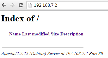
I first tried directly going to the Cloud9 page but alas, I guess that’s not a part of this image:

gett

This did work on my last debian. I hope I am not messing something up.

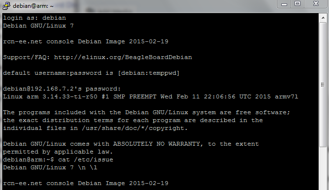
Next resort was to go with [ PuTTy ], as I am on a Windows computer.

imageversion

And lolwut

responsibility

This was followed by the usual process for logging into the network, and then apt-get update and apt-get upgrade.

Upgrade failed somewhere. Ran again. Nothing to upgrade…

Proceeding to our new Edimax wi-fi adapter’s drivers!

[ tutorial ] and key steps:

$ lsusb

greprtl

Anyway, this was followed by unsuccessful attempts on getting wifi up and running. My dongle is lit up, but  that’s all. Haven’t been able to get nmcli and /sbin/iw to work just yet.

Next was the most important thing for today, checking if the PRU package shows up:

fml

[ E: can’t locate package ]

Well, in that case. GitHub?

[ element14 assembler ]

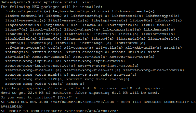
But first, I decided to resolve the wi-fi problem using the GUI route. I remembered using startlxde on R-Pi, and it turns out that Debian has startx to do that too. But my image didn’t come by startx, so I had to apt-get it (that is, apt-get xinit)

xinit

The workaround was to remove the lock on the archives.

Solution ]:

If you encounter with the same error, do the following steps.

Run the following command to unlock the apt package managers.

# rm /var/cache/apt/archives/lock

Now update the sources list using command:

# apt-get update 

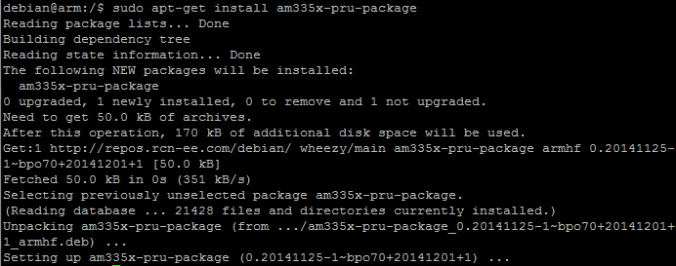
I wonder if there was a good reason for having the lock in the first place. Now apt-get was able to find the PRU package!

pru_package