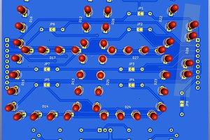
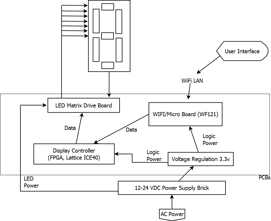
The scoreboard system consists of several main components. First the main power supply will be an off the shelf, 12v supply of sufficient current to drive the LED display. The second stage will be the logic power supply, that will create the voltages required by the digital components of the display. Third, the main controller and WiFi module, specifically the Bluegiga WF121, which serves as a stand alone WiFi module with integrated network stack, as well as providing an onboard PIC32 processor that can be programmed. Fourth, a matrix display driver implemented in an FPGA (a Lattice ICE40) will provide a means for controlling the display, and last, a array of MosFETs will be used to switch the LED matrix drive lines.
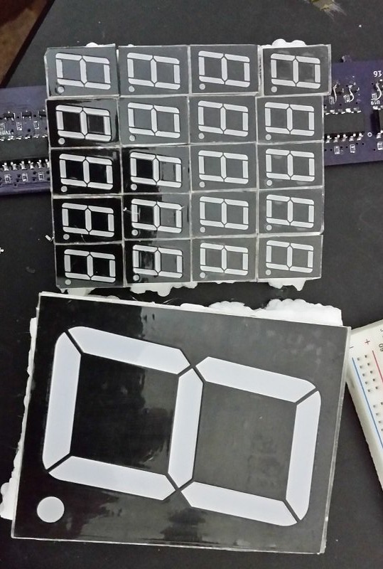
The scoreboard itself will consist of a time display (4 digits), a match score (4 digits) a team score (4 digits), and a period (1 digit). The digits will consist of 12V LED strips, cut into 10 cm segments, giving a 10cm x 20cm ish 7 segment digit.
An additional openness goal of this project is that it the main components will be reuseable and extendable to any LED display.
Unless otherwise noted, or where otherwise restricted, all original work contained herein is released in the public domain. No other licensing or copyright restrictions apply, unless required to include other works.

 Thinking about it more, while I'll complete the mutliplexed display test, when building larger displays, it may be more troublesome to run the 8 power wires to each digit, then it would be to run 2 power wires and 3 signal wires with some local circuitry to drive each digit. I'm thinking possibly a BCD decoder and a shift register to power each digit, feeding the serial out to the next digit. In that way the display could be refreshed by sending 72 bits, rather than constantly having to drive the multiplexed display.
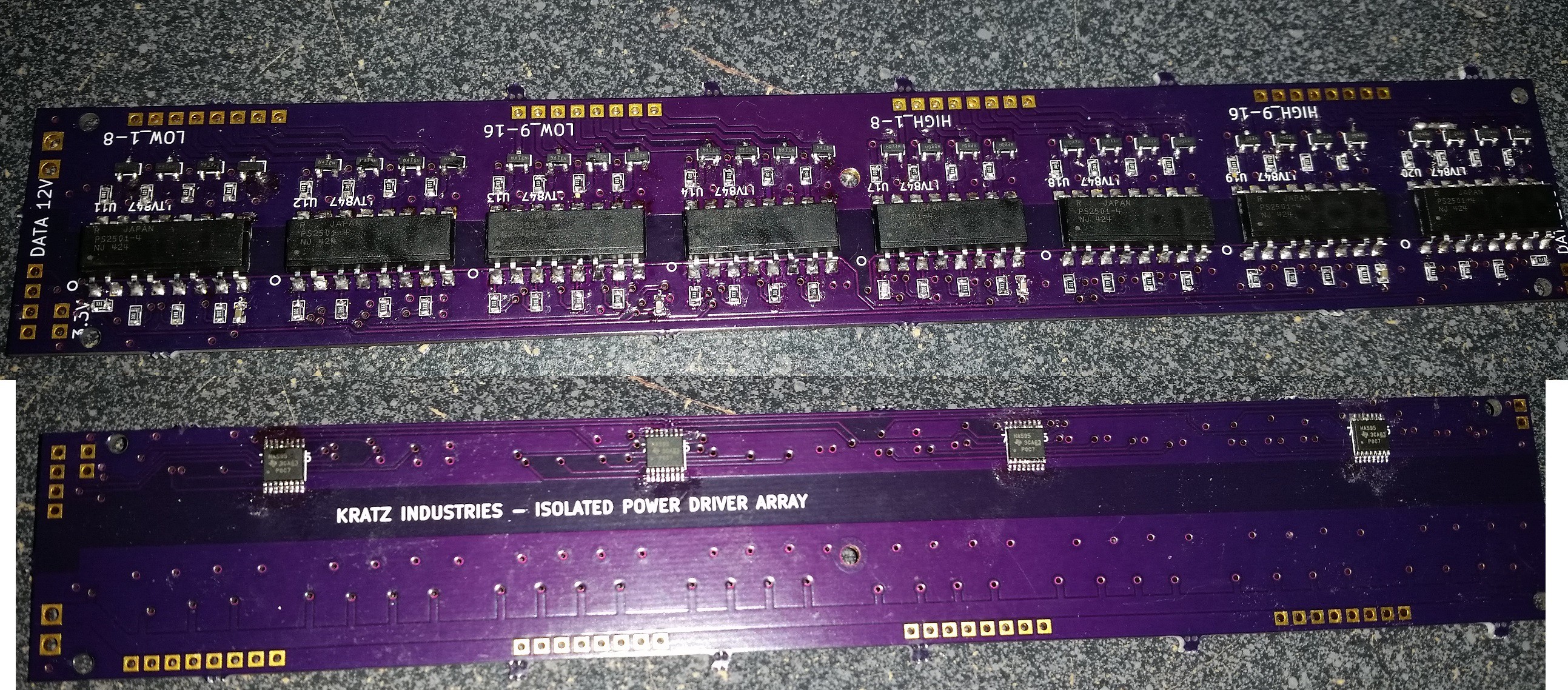
 Stephen Holdaway
 zakqwy
 Ken Yap