Nicolas BERTRAND
Once the hardware part of the Led driver was done, it remains to be compatible with T300K protocol so both devices can be driven by LedEdit 2014.
The capture of the the data sent by LedEdit are composed of 24 packets of 1040 bytes for the data and packets to acknowledge the presence. Based on the capture all data seamed pretty accessible, but each time a live steam with full black was generated the values changes and were not 0. The other point was when driving only one output all data were impacted. I did search for quite a time, even with the de-complied code that was given to me.
It turn out that I was so focus to find the LED data order one output after the other, I could have missed that the 8 ports are present vertically, in each byte. First byte is LSB, 8th, the MSB of the first color, red, for each output, the 8 next bytes, the second color green, same for blue with the 8 next bytes, this repeated 1024 give the whole data for a strip of 1024 LEDs per port.
With a bit more distance, it make sense to send the data this way. For small processor they just have to take the value and flush it into the GPIO register to bit bang the Neopixel protocol at 800Khz for 8 outputs.
The data packet starts with the byte 0x88, data, indicating the message type, followed by the packet index between 0 and 23 when in 1024 LED by channels (0 to 11 in 512 mode). Next 10 bytes is a random array generated at each live stream to compute the offset value of the data. The offset value is the same over all the live session. The offset can be generate with the calculation :
uint8_t key[]={59,129,197,228,81,208,127,174,99,41}; int i; uint8_t sum=0; for(i=0;i<10;i++) sum += msg.salt[i] ^ key[i]; offset = sum ^ 90; For each frame, the offset needs to be subtracted for the 1024 byte and then adjusted in the desired manner to be manipulated as RGB values for each LED.
The flush packet start with the bye 0xAA followed by the format in ASCII "rzbv001", next byte is the controller ID beginning at 1, encoded as uint16_t little endian to inform of 0x6000, 24576 in 1024 LED per channels or 0x3000, 12288 in 512 LED per channels. The 15th byte for this 65 bytes packet is the period of 50 milliseconds for 20fps. The rest of the bytes remains quite mysterious for the moment. When the live stream is stop from LedEdit the 0xAA packet is much smaller then 65 bytes, only 5.
In order to advertise the presence as "Normal" on LedEdit, the packet 0x55 is sent with the fist byte set as the device ID followed by 3 bytes set to zero.
Once this protocol was decrypted we could made use of the data in numerous ways to drive relay state, DMX projector colors, even WLED control with UDP Realtime protocol.
The Linux application allows the configuration of the board and manage the reception for LedEdit data. Some strip doesn't have the same color order, the application can swap byte to match the same color. There is also test mode that can be activated over the web page to generate color over a selected range of led of a specific output.
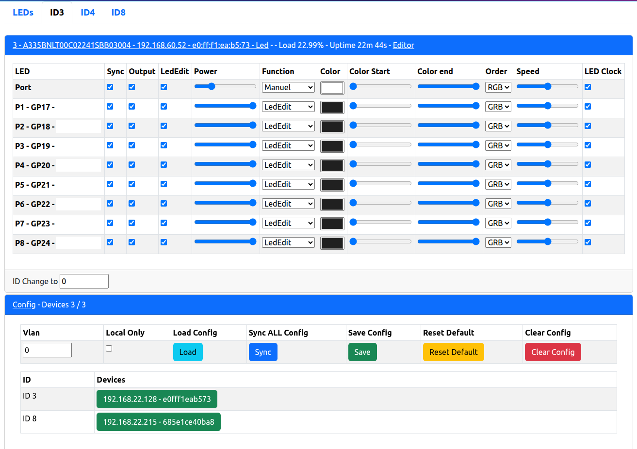
The other challenge was to distribute the configuration over the BBB so if one failed, the spare with no configuration should be able to receive the last configuration from this neighbor. The first implementation of this was with SSDP protocol then refined with MDNS to be able to advertise presence with more information and quicker synchronization.
 Ron O'Sullivan
 Henryk Plötz
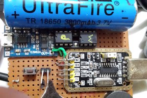
 Marcrbarker